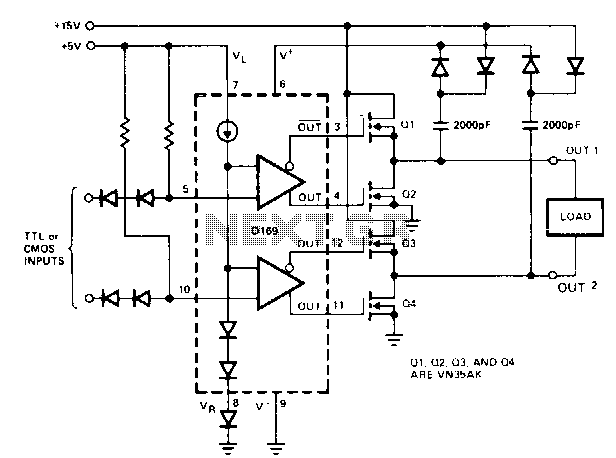


May be attached to the output of the driving gate.ī) The higher the number of gates attached to the output, the more frequently they will have Increases the capacitive loading also increases, thereby limiting the number of loads that

Why is the fanout of CMOS gates frequency dependent? 17) _Ī) The input gates of the FETs are predominantly capacitive, and as the signal frequency

16) _Ī) the logic gates must be given a short break during each clock cycle or else they willī) it is a measure of how long the clock must be applied to the gate before it will make theĬ) it limits the maximum operating frequency of a gateĭ) all the gates in a system must have the same propagation times in order to be compatible Propagation delay is important because _. The HIGH logic level for a standard TTL output must be at least _ V. Choose the one alternative that best completes the statement or answers the question.ġ4) The LOW logic level for standard TTL input cannot exceed _. NMOS devices use MOSFETs to implement the full range of logic functions using the universal 10) _ĭue to the extremely low power requirements of CMOS logic circuits, any number of CMOS andĮCL gates are noted for their high frequency capability and low-amplitude output voltage. The fanout of CMOS gates is frequency dependent. 8) _ĬMOS circuits utilize enhancement-mode MOSFETs. The TTL HIGH level source current is higher than the LOW level sinking current. The term open-drain means that the drain terminal of the output transistor is not internally Most TTL gates contain a totem-pole output circuit. The data sheet for the 74 series of TTL ICs shows that has a range of 4 V to 5 V. Propagation delay time is the time delay between an input signal causing an output signal. The average power dissipation for TTL can be calculated using PD = VCCICC. Write 'T' if the statement is true and 'F' if the statement is false.ġ) The nominal value of the dc supply voltage for TTL devices is +3.


 0 kommentar(er)
